Call Us

We are ready to help

Request a special version

Didn't find what you were looking for?
This field cannot be empty.
This field must be at least 3 characters long.

Files

Drag & Drop files here or click to browse

File format supported: (.pdf, .zip, .docx, .png, .jpg .xlsx, .xls, .csv, .txt) & Max Filesize: 25mb

Need to be uploaded up 1 to 3 files.
File format supported: (.pdf, .zip, .docx, .png, .jpg .xlsx, .xls, .csv, .txt) & Max Filesize: 25mb
Leave your details so we can contact you
This field cannot be empty.
This field must be at least 3 characters long.
This field cannot be empty.
Please enter a valid email address.
This field cannot be empty.
Please enter a valid phone number.
This field cannot be empty.
Server error. Try again later.
Thank you!
We will send you a confirmation email and will contact you soon.
Don't have account yet? Register
Back to shopping

Smartphone App for Configuration

A free app for the GSV-5H measuring amplifier is available on the Google Play Store and the Apple App Store. The app is used to configure the threshold generator, measuring range, output signal (voltage or current), and the low-pass filter.

Connection Assignment

The sensor is connected to the upper terminal blocks. The sensor power supply -Us/+Us is connected to terminals 2 and 3.
For sensors with 6-wire technology, the sensor leads -Uf/+Uf for the sensor power supply are connected to terminals 1 and 4.
Important: For sensors with 4-wire technology, jumpers must be installed from -Us to -Uf and +Us to +Uf.
The sensor signal +Ud/-Ud is connected to terminals 5 and 6. The sensor shield Sh is connected to terminal 8.

The operating voltage +Vsup, GNDsup (9V DC ... 28V DC) is connected to terminals 17 and 18.

The output signal Out, GND is taken from terminals 13 and 14.

Functions

ZERO

The "ZERO" function (zeroing function) performs an automatic zero adjustment. When the "Zero" function is executed, the difference between the currently displayed "actual value" and the configured "zero signal" is subtracted from the "actual value." This difference is permanently stored in non-volatile memory and is retained even after an interruption of the operating voltage. The "ZERO" function is triggered on the falling edge when the "ZERO" input is connected to operating voltage (or at least 5V) for at least 2 seconds. During the high level at the "ZERO" input (terminal 19), the front-panel ZERO (TARA) LED illuminates. SHUNT The "SHUNT" function triggers a "calibration jump" (self-test) at the measuring amplifier. A 642 kΩ resistor is connected across the -Ud and -Us inputs. This adds 100 kΩ in parallel to the resistor R2 of the connected sensor. When the self-test is active, a positive signal is output. The output signal level depends on the individual resistance R2 of the sensor. Sensors are typically manufactured with 350-ohm strain gauges. The table shows typical output signals for different sensor variants:

120 Ohm 0.05 mV/V
350 Ohm 0.14 mV/V
700 Ohm 0.24 mV/V
1000 Ohm 0.39 mV/V

By adding series resistors to compensate for temperature drift (40-ohm nickel resistors for aluminum sensors or 20-ohm resistors for steel sensors) or additional series resistors to calibrate the sensor to standardized values ​​of, for example, 1 mV/V or 2 mV/V, the output signals shown in the table can be reduced by approximately 10–20%.

The shunt test allows testing of the entire measurement chain from the measuring amplifier, through the connecting cable, to the sensor strain gauge.

Threshold Encoders / Switching Outputs

The GSV-5H measuring amplifier has two threshold encoders (SW1 and SW2). When the condition for a threshold encoder is met, the corresponding Switching output closed, i.e., the connection between SW1a and SW1b or SW2a and SW2b is closed. The maximum switching current of these "semiconductor relays" is 0.5 A, and the maximum switching voltage is 60 V. The switching thresholds for turning on (TH1 U Threshold 1 Upper) and turning off (TH1 L Threshold 1 Lower), or TH2 U and TH2 L, are specified as a percentage of the measuring range. The value for the "upper switching threshold" (TH1 U, TH2 U) must be greater than the value for the lower switching threshold (TH1 L, TH2 L). Four different types of threshold encoders can be configured: Hyst: With this type, the switching output is closed when the threshold is exceeded. HystInv: With this type, the switching output is opened when the threshold is exceeded.

  • Win: With this type of window comparator, the switching output is closed as long as the signal remains within the defined thresholds.
  • WinInv: With this type of window comparator, the switching output is opened when the signal remains within the defined thresholds.

Front LED

The front LEDs indicate

  • "Power Supply"
  • "Error"
  • "Threshold 1" Output active
  • "Threshold 2" Output active
  • "Zero" Input active (> 5V ... 28V)
  • "Shunt" Input active (> 5 ... 28V)

The The blinking patterns of the error LED indicate various types of errors.

Funktionen

ZERO

Die Funktion "ZERO" (Nullsetzfunktion) führt einen automatischen Nullabgleich durch. Beim Ausführen der "Zero Funktion wird die Differenz zwischen aktuell angezeigtem "Istwert" und dem konfigurierten "Nullsignal" wird vom "Istwert" subtrahiert. Diese Differenz wird im nichtflüchtigen Speicher dauerhaft abgelegt und auch nach einer Unterbrechung der Betriebsspannung berücksichtigt.

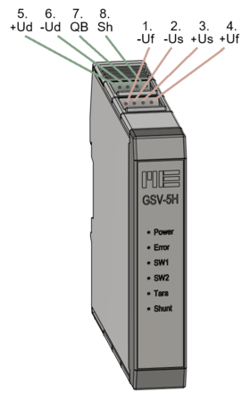
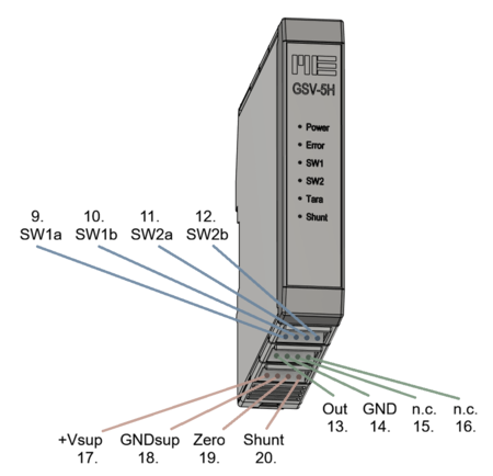
Die "ZERO" Funktion wird auf die fallende Flanke ausgelöst, wenn der Eingang "ZERO" für mindestens 2 Sekunden mit Betriebsspannung (oder mindestens 5V) verbunden ist. Während des High Pegels am Eingang "ZERO" (Klemme 19) leuchtet die frontseitige ZERO (TARA) LED.

SHUNT

Die Funktion "SHUNT" löst einen "Kalibriersprung" (Selbsttest) am Messverstärker aus. Dabei wird ein 642 kOhm Widerstand auf die Eingänge -Ud und -Us geschaltet. Damit werden 100 kOhm zum Widerstand R2 des angeschlossenen Sensors parallelgeschaltet. Bei aktivem Selbsttest wird am Ausgang ein positives Signal angezeigt. Die Höhe des Ausgangssignals richtet sich nach dem Einzelwiderstand R2 des Sensors. In der Regel werden Sensoren mit 350 Ohm Dehnungsmessstreifen gefertigt. Die Tabelle zeigt typische Ausgangssignale für verschiedenen Sensorvarianten:

120 Ohm 0,05 mV/V
350 Ohm 0,14 mV/V
700 Ohm 0,24 mV/V
1000 Ohm 0,39 mV/V

Durch zusätzliche Vorwiderstände zur Kompensation der Temperaturdrift (Nickel Vorwiderstände von 40 Ohm bei Sensoren aus Aluminium oder 20 Ohm bei Sensoren aus Stahl) oder zusätzliche Vorwiderstände zum Abgleich des Sensors auf standardisierte Kennwerte von z.B. 1 mV/V oder 2 mV/V können die in der Tabelle angezeigten Ausgangssignale um ca. 10....20% geringer ausfallen.

Mit dem Shunt Test wird ein Test der kompletten Messkette vom Messverstärker übder das Anschlusskabel bis zum Sensor-Dehnungsmessstreifen ermöglicht.

Schwellwertgeber / Schaltausgänge

Der Messverstärker GSV-5H verfügt über zwei Schwellwertgeber (SW1 und SW2) Wenn die Bedingung für einen Schwellwertgeber erfüllt ist, wird der zugehörige Schaltausgang geschlossen, d.h. die Verbindung zwischen SW1a und SW1b bzw. SW2a und SW2b ist geschlossen. Der maximale Schaltstrom dieser "Halbleiter- Relais" ist 0,5A, die maximale Schaltspannung ist 60 V.

Die Schaltschwellen für Einschalten (TH1 U Threshold1 Upper) und das Ausschalten (TH1 L Threshold1 Lower)  bzw TH2 U und TH2 L werden in % des Messbereichs angegeben. Der Wert für die "obere Schaltschwelle" (TH1 U, TH2 U) muss größer sein als der Wert für die untere Schaltschwelle (TH1 L, TH2 L). 

Es lassen sich 4 verschiedenen Typen von Schwellwertgebern konfigurieren:

  • Hyst: Bei diesem Typ wird der Schaltausgang bei Überschreitung geschlossen
  • HystInv: Bei diesem Typ wird der Schaltausgang bei Überschreitung geöffnet
  • Win: Bei diesem Typ Fensterkomparator wird der Schaltausgang geschlossen, solange sich das Signal innerhalb der definierten Schwellen bewegt.
  • WinInv: Bei diesem Typ Fensterkomparator wird der Schaltausgang geöffnet, wenn sich das Signal innerhalb der definierten Schwellen bewegt.

Frontseitige LED

Die frontseitigen Leuchtdioden signalisieren

  • "Versorgungsspannung" (Power), 
  • "Fehler" (Error)
  • "Schwellwert 1" Ausgang aktiv
  • "Schwellwert 2" Ausgang aktiv
  • "Zero" Eingang aktiv  (> 5V ... 28 V)
  • "Shunt" Eingang aktiv ( > 5... 28 V)

Die Blinkmuster der Error LED sind verschiedenen Fehlerzusänden zuzuordnen:

  • dauerhaft ein: Leitungsbruch oder Sensor Defekt; UD-Test fehlgeschlagen, d.h. <1,25V oder >3,5V oder |+Ud--Ud| > 40mV In diesem Fehlerzustand werden die Schwellwertschalter nicht bedient und TARA nicht ausgefuehrt.
  • Blinken mit 0,5 Hz (2 Sek an, 2 Sek aus): Fehler im NFC-Konfigurationsfile
  • Blinken mit 1 Hz: Fehler am Spannungsausgang, i.d.R. wegen Kurzschluss am Ausgang
  • Blinken mit 2 Hz: Fehler am Stromausgang, i.d.R. weil Stromschleife offen oder Kombination mehrere Fehler
  • Blinken mit 4 Hz: Ausgangstreiber ueberhitzt

GSV-5H

Messverstärker zur Montage auf Hutschiene mit 2 Schwellwertgebern, Shunt Selbsttest Funktion, automatischen Nullabgleich, einstellbaren Filtern von 30Hz bis 10 kHz, "echt" analogem Signalpfad, Einstellung des Messbereichs in 4 Stufen 0,5 mV/V, 1 mV/V, 2 mV/V und 4 mV/V, Stromausgang oder Spannungsausgang, Einstellbarem Offset, ...

GSV-5H
bars-filter