Call Us

We are ready to help

Request a special version

Didn't find what you were looking for?
This field cannot be empty.
This field must be at least 3 characters long.

Files

Drag & Drop files here or click to browse

File format supported: (.pdf, .zip, .docx, .png, .jpg .xlsx, .xls, .csv, .txt) & Max Filesize: 25mb

Need to be uploaded up 1 to 3 files.
File format supported: (.pdf, .zip, .docx, .png, .jpg .xlsx, .xls, .csv, .txt) & Max Filesize: 25mb
Leave your details so we can contact you
This field cannot be empty.
This field must be at least 3 characters long.
This field cannot be empty.
Please enter a valid email address.
This field cannot be empty.
Please enter a valid phone number.
This field cannot be empty.
Server error. Try again later.
Thank you!
We will send you a confirmation email and will contact you soon.
Don't have account yet? Register
Back to shopping

Synchronisation

Fieldbuses such as EtherCat or CANbus are particularly suitable for synchronizing measurement data from different measurement systems. In these cases, synchronization can be achieved via the EtherCat master or, for example, using special commands such as "CAN-Sync."

For the synchronization of measuring amplifiers with USB interface or Bluetooth interface, the "Master" and "Slave" modes are available for some measuring amplifiers.

In this case, synchronization between two or more devices is achieved via digital inputs and outputs: The measuring amplifier, which is configured as the "master", accompanies each measured value with an edge at the digital output.

One or more measuring amplifiers configured as slaves send a measured value with each signal edge at the digital input.

The GSV-4 and GSV-8 measuring amplifiers have this function.

Synchronisation von GSV-4USB

GSV-4USB

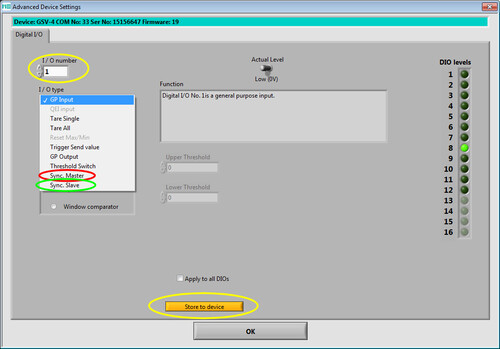
To synchronize two GSV-4USBs, one device is configured as "master" and one device as "slave".

The "master" sends a digital pulse to the selected digital output with each measured value.

The "slave" sends a measured value via the USB interface whenever it receives a pulse at the digital input.

In this operating mode it is important that "Master" and "Slave" are set to the same data frequency.


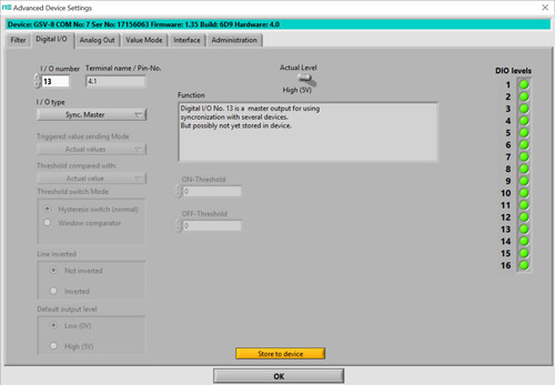
GSV-8 Master

Configuring the GSV-8 as a master. This setting is only possible for digital inputs and outputs 13 to 16.

The synchronization cable with SubD25 sockets connects DIO16 (pin 13) and DGND (pin 5) between two GSV-8DS;

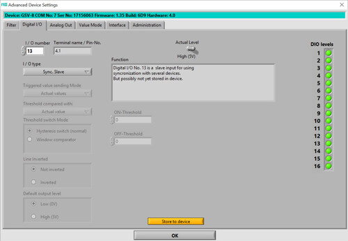
GSV-8 Slave

Configuring the GSV-8 as a slave. This setting is only possible on digital inputs/outputs 13 to 16.

External trigger signal

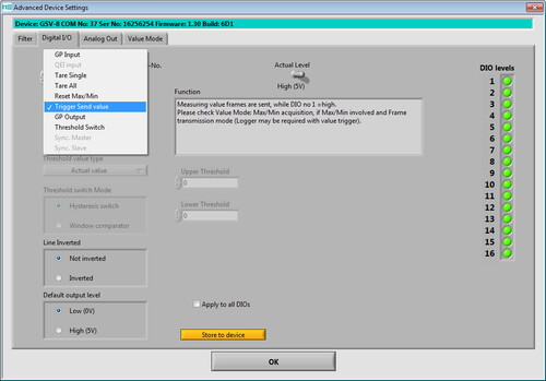
Another method for triggering data acquisition is to apply a common start pulse to all devices.

With this configuration, the GSV-8 transmits measured values ​​at the set data frequency as long as a high level is present at digital input 1.

Software Trigger

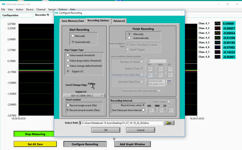
The GSVmulti software has a function that allows recording to be started via a digital signal.

In this configuration, the GSVmulti software starts recording when a falling edge is registered at digital output 2.

bars-filter