Call Us

We are ready to help

Request a special version

Didn't find what you were looking for?
This field cannot be empty.
This field must be at least 3 characters long.

Files

Drag & Drop files here or click to browse

File format supported: (.pdf, .zip, .docx, .png, .jpg .xlsx, .xls, .csv, .txt) & Max Filesize: 25mb

Need to be uploaded up 1 to 3 files.
File format supported: (.pdf, .zip, .docx, .png, .jpg .xlsx, .xls, .csv, .txt) & Max Filesize: 25mb
Leave your details so we can contact you
This field cannot be empty.
This field must be at least 3 characters long.
This field cannot be empty.
Please enter a valid email address.
This field cannot be empty.
Please enter a valid phone number.
This field cannot be empty.
Server error. Try again later.
Thank you!
We will send you a confirmation email and will contact you soon.
Don't have account yet? Register
Back to shopping

Stress analysis with strain gauges

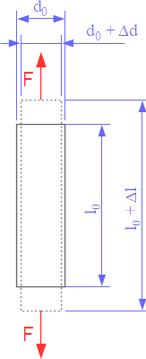
Stress analysis with strain gauges is used to determine the mechanical stress in a component.
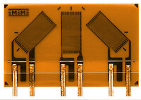
In stress analysis with strain gauges, bridge circuits with only one active measuring grid are usually used.

In a uniaxial stress state, it is sufficient to measure the strain with a single measuring grid if the direction of the mechanical stress is known. The strain gauge is used to determine the amount of strain. To calculate the mechanical stress from the measured strain,

  • the elastic modulus of the material and
  • the k-factor of the strain gauge

must be known.

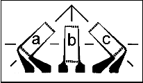
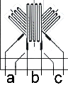
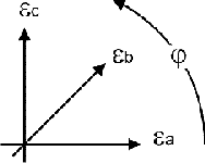
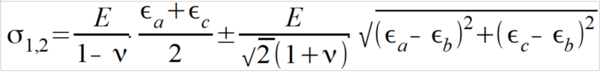
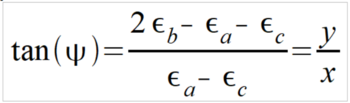
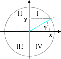
If the stress state is biaxial, the principal stresses and the direction of the principal stresses must be determined. Three determination equations are required to determine the three unknown quantities. Therefore, three measuring grids are used in three linearly independent directions, e.g. 0°, 45° and 90° or 0°, 60° and 120°.

For this task, strain gauge rosettes with three active measuring grids are available. To calculate the mechanical stress from the measured strain, the elastic modulus of the material, the Poisson's ratio of the material and the k-factor of the strain gauge must be known

Uniaxial stress state

The uniaxial stress state occurs, for example, in tension and compression bars as shown in Fig. 1.

In the case of a tension rod, the maximum tensile stress occurs in the direction of the force.

The following applies to the longitudinal direction:

σ1 = E · ε1 = E · Δ l / l0

A negative strain is measured in the direction of the transverse contraction. The transverse contraction is described by the Poisson ratio ν: ε2 = - ν · ε1.

The stress σ is a function of the angle φ to the longitudinal axis.

σ = f(φ) = 1/2 σmax ( 1 + cos(2φ) )

The mechanical stress perpendicular to the longitudinal axis is 0.

The stress state for the tension rod is uniaxial, the strain state is biaxial:


ε2 = - ν · ε1
ε1: Strain in the 1st main direction
ε2: Strain in the 2nd main direction (perpendicular to the 1st main direction)
ν: Poisson’s ratio

The strain ε is a function of the angle φ to the longitudinal axis:

ε = f(φ) = 1/2 ε1 [ ( 1 - ν + cos(2φ) (1 + ν) ]

Attention

  • The material stress may only be calculated from the equation σ = E ε if the strain was measured in the direction of force and the stress state is uniaxial.

  • In the transverse direction, a strain is measured even though no mechanical stress is present.

Biaxial stress state

In the biaxial stress state, the maximum stresses occur in two mutually perpendicular directions. These directions are called principal stress directions, indexed with 1 and 2.

As a rule, the main stress directions are not known in stress analysis.

In this case, a stress analysis is carried out using rosettes.

The strain gauge rosette is used to measure the strain in three directions “a”, “b” and “c”.

The grids “b” and “c” are each oriented by 45° and 90° counterclockwise relative to the measuring grid “a” (alternatively, measuring grids 0, 60° and 120° are also used).

The angle j denotes the angle between the measuring grid a and the first main direction.

For the 90° rosette (0°, 45°, 90°) the following relationship applies to determine the principal stresses s1 and s2:

To determine the angle j a case distinction must be made based on the following calculation:

Case distinction for determining the auxiliary angle y (PSI) from the measured strains:

Due to the ambiguity of the tangent function, it is now necessary to determine, based on the case distinction, in which of the quadrants I to IV the solution for the desired angle j is located:

y = 2 εb - εa - εc   y ≥ 0 y > 0 y ≤ 0 y < 0
x = εa - εc x > 0 x ≤ 0 x < 0 x ≥ 0
Quadrant I II III IV
Hauptrichtung φ = 1/2 · (0° + |ψ|) φ = 1/2 · (180° - |ψ|) φ = 1/2 · (180° + |ψ|) φ = 1/2 · (360° - |ψ|)

Table 1: Determination of the angle φ from the auxiliary angle ψ based on a case distinction.
Note: the absolute value of ψ is used.

DMS-Messverstärker für die Spannungsanalyse

ME-Meßsysteme fertigt die geeigneten Elektronikgeräte für die Verstärkung und Auswertung von den DMS-Signalen:

GSV-8 8-Kanal Messverstärker

GSV-1A4 4-Kanal Messverstärker

GSV-6BT 6-Kanal Messverstärker

GSV-2TSD-DI digitaler 1-Kanal Display-Messverstärker

GSV-2MSD-DI digitaler 1-Kanal Display-Messverstärker

GSV-1H-QB analoger 1-Kanal Messverstärker

learn more

Literatur

Linksammlung im Forum: linksammlung-spannungsanalyse

In den TechNotes von Vishay werden die Grundlagen der DMS Rosetten dargestellt. Die Gitter "a", "b", "c" sind hier jedoch mit "1", "2", "3" indiziert:
TechNote-515: TN-515-Rosetten_de.pdf
TechNote-512-1: TN-512-1-Schubspannungs_Messung_de.pdf


bars-filter