Devices with interface or digital display
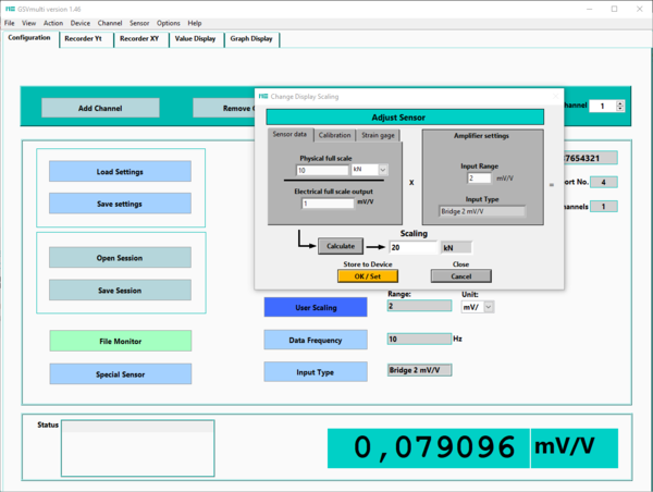
Force sensors and torque sensors are equipped with strain gauges in a bridge circuit. When a force or torque is applied, the output signal of the bridge circuit changes.
The output signal of the bridge circuit is usually specified as the voltage ratio Ud/Us: "differential signal Ud" relative to the "supply voltage Us"
CV characteristic
During sensor calibration, the slope of the sensor characteristic curve is determined. This slope is indicated on the test reports or calibration certificates as the so-called "characteristic value" (CV).
The characteristic value is the output signal Ud/Us of the bridge circuit at the sensor's nominal force (or torque), minus the sensor's zero signal. The output signal of the bridge circuit is specified as the voltage ratio Ud/Us.
Nominal force divided by characteristic value is a straight line through the origin (0,0) of the coordinate system. The unit of the characteristic value is mV/V, and in a 2-point calibration, the characteristic value is determined at the nominal force.
Nominal force FN
The sensor is designed for the nominal force FN (or nominal torque MN). Calibration is usually performed at nominal force or at partial loads, e.g., from 20%.
Input measuring range MR
The measuring amplifier converts the differential signal Ud of the Wheatstone bridge into a digital signal. It provides the required supply voltage Us for the sensor's Wheatstone bridge. The input measuring range MR for the voltage ratio Ud/Us is usually fixed to, for example, 2.0000 mV/V or 3.5000 mV/V, or can be adjusted in specific steps using a jumper or configuration software. The input measuring range MR is usually specified on the measuring amplifier's nameplate.