The GSV-5H is a high-performance strain gauge amplifier in a slim DIN rail housing for industrial applications where precise measurements must be reliably converted into a standard signal. In its default configuration, the amplifier features a ±10 V analog output with a measuring range of 2 mV/V bridge misalignment, making it immediately compatible with many strain gauge sensors, such as force sensors, torque sensors, strain gauges, and other strain gauges.
Thanks to its compact design and 20 plug-in/spring-loaded terminals, the device can be installed quickly and securely in control cabinets.
A key advantage: The GSV-5H is designed so that important parameters can be conveniently configured via the "GSV-5H" app. This allows users to flexibly adapt the amplifier to different requirements – for example, switching the analog output to 4–20 mA, selecting the offset to suit downstream processing, or precisely adjusting the cutoff frequency to the dynamics of the application.
In addition, four measuring ranges are available, making the GSV-5H suitable for various strain gauge sensors. With two threshold outputs and a tare function via control line, it is also ideally suited for practical automation tasks.
Smartphone App for Configuration
A free app for the GSV-5H measuring amplifier is available on the Google Play Store and the Apple App Store.
The app is used to configure the threshold generator, measuring range, output signal (voltage or current), and the low-pass filter.
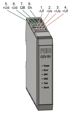
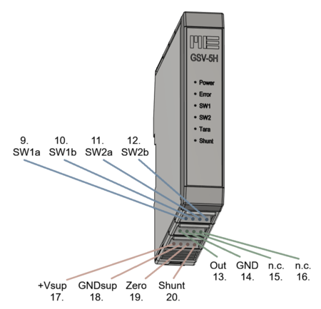
Connection Assignment
The sensor is connected to the upper terminal blocks. The sensor power supply -Us/+Us is connected to terminals 2 and 3.
For sensors with 6-wire technology, the sensor leads -Uf/+Uf for the sensor power supply are connected to terminals 1 and 4.
Important: For sensors with 4-wire technology, jumpers must be installed from -Us to -Uf and +Us to +Uf.
The sensor signal +Ud/-Ud is connected to terminals 5 and 6. The sensor shield Sh is connected to terminal 8.
The operating voltage +Vsup, GNDsup (9V DC ... 28V DC) is connected to terminals 17 and 18.
The output signal Out, GND is taken from terminals 13 and 14.
Functions
ZERO
The "ZERO" function (zeroing function) performs an automatic zero adjustment. When the "Zero" function is executed, the difference between the currently displayed "actual value" and the configured "zero signal" is subtracted from the "actual value." This difference is permanently stored in non-volatile memory and is retained even after an interruption of the operating voltage. The "ZERO" function is triggered on the falling edge when the "ZERO" input is connected to operating voltage (or at least 5V) for at least 2 seconds. During the high level at the "ZERO" input (terminal 19), the front-panel ZERO (TARA) LED illuminates. SHUNT The "SHUNT" function triggers a "calibration jump" (self-test) at the measuring amplifier. A 642 kΩ resistor is connected across the -Ud and -Us inputs. This adds 100 kΩ in parallel to the resistor R2 of the connected sensor. When the self-test is active, a positive signal is output. The output signal level depends on the individual resistance R2 of the sensor. Sensors are typically manufactured with 350-ohm strain gauges. The table shows typical output signals for different sensor variants:
| 120 Ohm |
0.05 mV/V |
| 350 Ohm |
0.14 mV/V |
| 700 Ohm |
0.24 mV/V |
| 1000 Ohm |
0.39 mV/V |
By adding series resistors to compensate for temperature drift (40-ohm nickel resistors for aluminum sensors or 20-ohm resistors for steel sensors) or additional series resistors to calibrate the sensor to standardized values of, for example, 1 mV/V or 2 mV/V, the output signals shown in the table can be reduced by approximately 10–20%.
The shunt test allows testing of the entire measurement chain from the measuring amplifier, through the connecting cable, to the sensor strain gauge.
Threshold Encoders / Switching Outputs
The GSV-5H measuring amplifier has two threshold encoders (SW1 and SW2). When the condition for a threshold encoder is met, the corresponding Switching output closed, i.e., the connection between SW1a and SW1b or SW2a and SW2b is closed. The maximum switching current of these "semiconductor relays" is 0.5 A, and the maximum switching voltage is 60 V. The switching thresholds for turning on (TH1 U Threshold 1 Upper) and turning off (TH1 L Threshold 1 Lower), or TH2 U and TH2 L, are specified as a percentage of the measuring range. The value for the "upper switching threshold" (TH1 U, TH2 U) must be greater than the value for the lower switching threshold (TH1 L, TH2 L). Four different types of threshold encoders can be configured: Hyst: With this type, the switching output is closed when the threshold is exceeded. HystInv: With this type, the switching output is opened when the threshold is exceeded.
- Win: With this type of window comparator, the switching output is closed as long as the signal remains within the defined thresholds.
- WinInv: With this type of window comparator, the switching output is opened when the signal remains within the defined thresholds.
Front LED
The front LEDs indicate
- "Power Supply"
- "Error"
- "Threshold 1" Output active
- "Threshold 2" Output active
- "Zero" Input active (> 5V ... 28V)
- "Shunt" Input active (> 5 ... 28V)
The The blinking patterns of the error LED indicate various types of errors.