Display scaling
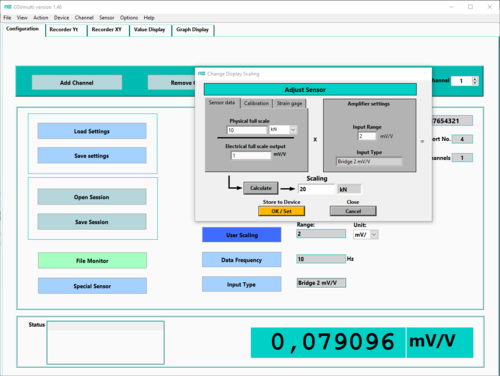
The “User Scaling” input mask is used to configure the measured value display.
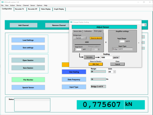
In this dialog, two different methods are offered for general sensors to adjust the measured values for specific sensor examples. There is a third method for individual strain gauges.
1. Using the “Sensor data” input mask, the display is configured based on the technical data of the sensor from the test report or from the calibration certificate.
The following data is required:
-
Measuring range of the sensor (Physical full scale)
-
Characteristic value (electrical full scale output)
-
Measuring range (input range) of the amplifier
2. Using the “Calibration” input mask, the scaling factor can be determined using a known test load. To do this, it must be possible to free the sensor from the payload to be measured and then apply the test load. This procedure corresponds to a 2-point calibration in which the first point is shifted to zero by the measuring amplifier.
The input range of the measuring amplifier is known to the configuration software in most GSV models because it is read from the EEProm of the measuring amplifier. In most cases the measurement range is 2 mV/V or 3.5 mV/V. For the GSV1A8 measuring amplifiers and possibly also the GSV-3, you must enter the input sensitivity (i.e. the electrical measuring range) under "Input Range" for all 3 methods. It is usually stated on the nameplate.
Calculate calculates the scaling factor to be programmed.
With OK/Set it is permanently saved in the measuring amplifier.
Attention: only the scaling factor and the unit are permanently stored in the measuring amplifier The unit to be displayed can be set in the Configuration tab, or under Menu Bar->Channel->Unit.
Some multi-component sensors such as K6D, F6D and K3R are not configured here, but in the "Special Sensors" dialog.


