Scaling the display

The "User Scaling" window is used to configure the measured value display.

In this dialog, two different methods are offered for general sensors in order to adjust the measured values for specific sensor specimens. There is a third method for individual strain gauges.

1. With the "Sensor data" input mask, the display is configured based on the technical data of the sensor from the test report or from the calibration certificate. The following data is needed:

• Nominal measuring range (Physical full scale)

• Electrical full scale output

• Eventually: Input Range of the amplifier

2. With the "Calibration" input mask, the scaling factor can be determined using a known reference load. To do this, it must be possible to free the sensor from the payload to be measured and then to apply the reference load. This procedure corresponds to a 2-point calibration, in which the first point is set to zero by the measuring amplifier, so that the characteristic curve is shifted parallel to the y-intercept =0.

The input measuring range is known to the software for most GSV models, since it is read out from the measuring amplifier. Most often it is 1, 2 or 3.5 mV/V. With the GSV1A8 measuring amplifier and possibly also with the GSV-3, you must enter the input sensitivity (i.e. the electrical measuring range) under "Input Range" for all three methods. It's usually specified on the type plate.

Calculate calculates the scaling factor to be programmed.

It is permanently stored in the measuring amplifier with OK/Set.

Attention please: Only the scaling factor and the unit are permanently stored in the measuring amplifier

The unit to be displayed can be set in the Configuration tab, or under Menu Bar->Channel->Unit.

Some multi-dimensional sensors like K6D, F6D and K3R are not configured here but in the "Special Sensors" dialog.

Enter the calibration data

"Sensor data" input mask for the calibration data of the sensor

Enter the physical measuring range of the sensor in "Physical full scale" in the unit in which you want to measure. If desired, you can select the unit here with the pull-down element. In "Electrical full scale output" enter the electrical characteristic value; its unit must correspond to that displayed to the right of "Input Range", for bridge sensors this is always mV/V.

Then click on "Calculate" to have the scaling calculated and then on "OK/Set" to save it in the measuring amplifier.

2-Point Calibration

The procedure of a 2-point calibration can be started in the "Calibration" tab.

For this purpose, the zero signal and the load signal are acquired at a precisely known test load, which is in the range of 10% ... 100% of the measuring range of the sensor. Test loads of 40% ... 100% are recommended.

Before starting the procedure, the measuring amplifier should be warmed up, i.e. switched on for some time (up to 30 minutes, depending on the model).

First you enter the value of the test load in "Calibration Load" in the unit to be measured. Then unload the sensor, click "Execute Calibration" and follow the instructions of the wizard. At the end click "OK/Set" to save the determined scaling factor in the measuring amplifier.

Scaling for strain gauges

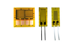
The display for the strain measurement with strain gauges (DMS) can be configured via the "Strain gage" tab. This could also be a preparation for the stress analysis, but the modulus of elasticity of the material would still have to be taken into account. The stress analysis with rosette strain gauges should better be configured under "Special Sensor"->"Calculate principal stress".

Here in "Strain gage" the scaling for the display of strain in µm/m is determined. The scaling factor is calculated from the k-factor (gage factor), the bridge type and the Poisson's ratio, provided bridge types with longitudinal and transverse grid patterns are used. Select one of the following bridge types with "Bridge type":

Full (4) : Full bridge with 4 strain gauges, without transverse grid
Half (2) : Half bridge with 2 strain gauges, without transverse grid
Quarter (1) : Quarter bridge with one strain gauge
Half (1+µ) : Half bridge with transverse grid, one longitudinal and one transverse
Full (2+2µ) : Full bridge with transverse grids, 2 longitudinal and 2 transverse

Enter the gage factor of the strain gage used in "Gage factor" and, if necessary, the Poisson's ratio under "Poissons ratio µ". Then click on "Calculate" to have the scaling calculated and then on "OK/Set" to save it in the measuring amplifier. Only with the GSV-2 device you can also save the individual gauge parameters in the device with "Store to device".