Wiring diagrams

The use of the Wheatstone bridge circuit offers three essential advantages:

  • compensation of the temperature-induced strain
  • zero adjustment of the output voltage
  • compensation of lateral forces and moments

By using total four measuring grids, the output signal can be increased by a suitable interconnection in comparison to the use of a single measuring grid.


Bending

The grids R1 and R3 are arranged on the top of the bending beam, the grids R2 and R4 are arranged on the underside of the beam. Temperature-related strain and srtain due to axial force or torsion are compensated in this circuit. Only the bend is detected around an axis.

The mechanical stress results from the beam height h, the beam width b (the resistance moment Wb = bh2/6 with a rectangular cross-section),

as well as the bending moment (Mb = F L) from the force F and the lever arm L:

σb = Mb / Wb

To measure the bending, strain gauges with two parallel grids are used:

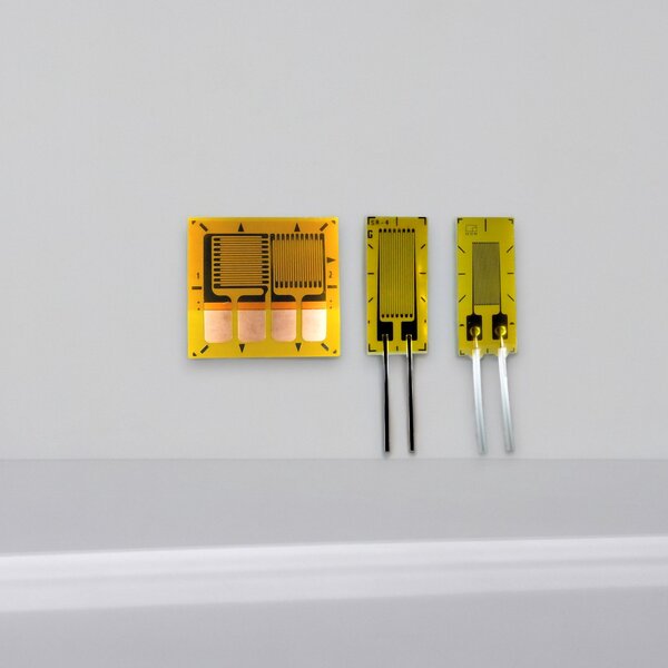
Strain gauge double grid 0 °-0 ° for measuring of the bending
DMS-Doppelgitter 0°-0° zur Messung der Biegung  


Axial force

In the case of the axial force, the strain gauges are arranged in the way, that the longitudinal and transverse expansions are measured. In contrast to the bending beam, the measuring grids R2 and R4 contribute only approx. 30% of the signal of the measuring grids R1 and R3. The same amount for the output signal: for the resistance change at R2: ΔR2/R2 = -ν ΔR1/R1.

Temperature-induced strain and strain due to bending or torsion are compensated for this circuit. Only the axial force is detected.

The mechanical stress results from the force F and the cross-sectional area A = b h:

σ = F / A

To measure the axial force, strain gauges are used with two mutually perpendicular grids (T-rosette) :

Strain gauge T-grid 0°-90° for measuring the axial force
T-Rosette 0°-90° zur Messung der Axialkraft  

The connection between grids R1 and R2 or R3 and R4 can already be carried out on the strain gauge carrier, so that only 3 soldering surfaces are required.

A small distance of the grids R1-R2 or R3-R4 is required to compensate the bending around the vertical axis.

In the case of small dimensions, it is recommended to install one grid per side surface, or an installation of one T-rosette per side surface with series connection of two grids each.


Torsion

The maximum strains in a torsion bar are less than 45 ° to the shaft axis. By the arrangement of two measuring grids under +45 ° and -45 °, a bridge circuit with two positively and two negatively stretched grids can be realized similar to the bending stress.

Grid R1 is parallel to grid R3 and positively stretched at the right moment.

Grid R2 is parallel to grid R4 and negatively stretched ("compressed") at the right moment.

Temperature-induced strain and strain due to bending or axial force are compensated for this circuit. Only the torsion is detected.

The mechanical stress σt results from torsion moment Mt and the resistance moment Wt against torsion:

σt = Mt / Wt 

To measure the torsion, strain gauges with a +45/-45 grid arrangement are used.

The connection between grids R1 and R2 or R3 and R4 can already be carried out on the strain gauge carrier, so that only 3 soldering surfaces are required.

A simplified installation, in particular for shafts with large diameters (for example, ship shafts, generator drive shafts), is possible by using a strain gauge full bridge 4x45 °.

In the case of inhomogeneous voltage fluctuations, for example in the installation of strain gauges at a small distance from splines, the installation of 4 measuring grids on the circumference or 4 double grids in series connection is recommended.

Strain gauge grids for measuring of the torsion
 DMS-Vollbrücke mit 4 Messgittern 4x45° zur Messung der Torsion.

Shear

The maximum strains in a shear bar are below 45 ° in the area of ​​the neutral fiber.

By the arrangement of two measuring grids below + 45 ° and -45 °, a bridge circuit with two positively and two negatively stretched grids can be realized similarly to the bending and torsional stress.

Grid R1 and grid R3 are positively stretched.

Grid R2 and grid R4 are negatively stretched ("compressed").

Temperature-related strain and strain due to bending, axial force or torsion are compensated for this circuit. Only the shear is detected.

The mechanical stress σt results from the force F and the cross-section A = b h:

σ ≈ F / A * 1,4 

To measure the shear, strain gauges with a +45 / -45 grid arrangement are used (as for torsion).