Stress analysis with strain gauges

The stress analysis with strain gauge is used to determine the stress in a single component.
In the stress analysis with strain gauges usually bridge circuits are used with only one active measurement grid.

In a uniaxial stress condition, it is sufficient to detect the strain with a single measuring grid. The direction of the mechanical stress is required in this case, as known. The strain gauge is used to determine the amount of strain.

In order to calculate the mechanical stress from the measured elongation, it is essential to know

  • the modulus of elasticity of the material as well as
  • the k-factor of the strain gauge

If it is a two-axis voltage state, the main voltages and the direction of the main voltages should be determined. Three determination equations are required to determine the three unknown quantities. Therefore, three measuring grids are used in three linearly independent directions, e.g. 0°, 45° and 90° or 0°, 60° and 120°.

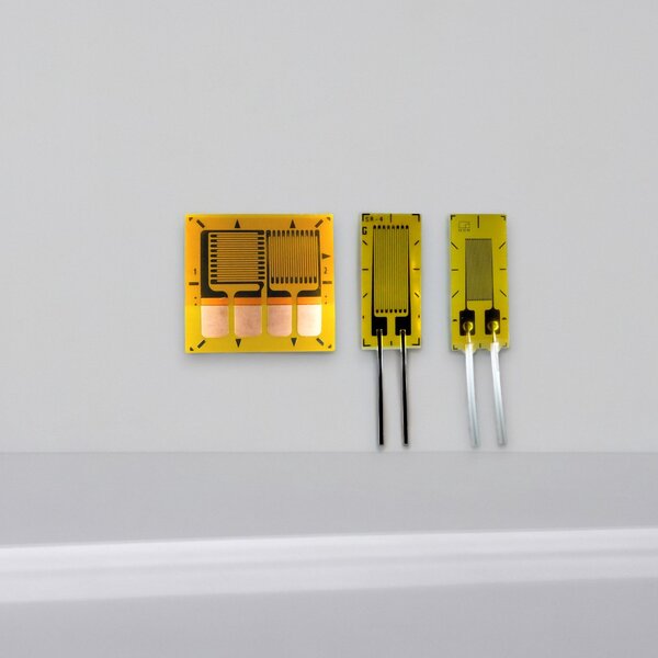
For this task there are straingage rosettes with three active measuring grids. For the calculation of the mechanical stress from the measured strain, the modulus of elasticity of the material, the cross contraction number of the material and the k-factor of the strain gauge must be known.

Uniaxial stress state

Pull rod / push rod

The uniaxial stress state occurs for example in tension and compression members as in Fig. 1

The tensile rod produces the maximum of the tensile stresses in the direction of the force.

For the longitudinal direction:

σ1 = E · ε1 = E · Δ l / l0

A negative elongation is measured in the direction of the transverse contraction. Cross-contraction is described by the Poisson number: ε2 = - ν · ε1.

The stress σ is a function of the angle  φ to the longitudinal axis.

σ = f(φ) = 1/2 σmax ( 1 + cos(2φ) )

The mechanical stress persecuting to the longitudinal axis is 0.

The stress state for the pull rod is single-axis, the strain state is two-axis:

ε2 = - ν · ε1
ε1: strain in the 1. main direction
ε2: strain in the 2. main direction (vertical to the 1st main direction)
ν: Cross-contraction number

The strain ε is a function of the angle  φ to the longitudinal axis:

ε = f(φ) = 1/2 ε1 [ ( 1 - ν + cos(2φ) (1 + ν) ]

Attention

  • The material stress may only be calculated from equation σ = E ε, if the elongation in the force direction has been measured and the stress state is single-axis.

  • In the transverse direction, a strain is measured, although there is no mechanical stress.

Two-axis stress state

In the two-axis stress state, the maximum stress occur in two directions perpenous to each other. These directions are called main stress directions, indexed with 1 and 2.

As a rule, the main stress directions are not known in the stress analysis.

In this case, a stress analysis is performed with rosettes.

With the straingage rosette, the strain is reduced in three directions "a", "b" and "c".

The grids "b" and "c" are each relative to the measuring grid "a" oriented by 45° and 90° counterclockwise respectively (alternatively, measuring grids 0, 60° and 120° are also used.)

The angle j denotes the angle between the measuring grid a and the first main direction.

For the 90° rosette (0°, 45°, 90°)  the following connection applies to the determination of the main voltages s1 and s2:

to determine the angle j, a case distinction must be made on the basis of the following calculation:

Case distinction for the determination of the auxiliary angle y (PSI) from the measured strains:

Due to the ambiguity of the tangens function, it is now necessary to determine the case distinction, in which of the quadrants I to IV the solution for the desired angle j is located:

y = 2 εb - εa - εc   y ≥ 0 y > 0 y ≤ 0 y < 0
x = εa - εc x > 0 x ≤ 0 x < 0 x ≥ 0
quadrant I II III IV
main direction φ = 1/2 · (0° + |ψ|) φ = 1/2 · (180° - |ψ|) φ = 1/2 · (180° + |ψ|) φ = 1/2 · (360° - |ψ|)

Table 1: Determination of the angle φ from the auxiliary angle ψ on the basis of a case distinction.
Note: the amount of ψ is applied.

Straingage amplifier for stress analysis

ME-Measurement Systems manufactures the appropriate electronic equipment for the amplification and evaluation of the straingage signals:

GSV-8 8-channel amplifier

GSV-1A4 4-channel amplifier

GSV-6BT 6-channel amplifier

GSV-2TSD-DI digital 1-channel display-amplifier

GSV-2MSD-DI digital 1-channel display-amplifier

GSV-1H-QB analog 1-channel amplifier

Literature

Links in Forum: Links-stress analysis

The "E-MechLAB" of the Institute of Applied Mechanics of the Technical University of Berlin presents the basics in a clear way:
types of voltages: normal and shear stresses
principal stress, reference stress, Mohr's stress circle: principal stresses, equivalent stresses

in the TechNotes Vishay be shown the basics of strain gauge rosettes. The Grid "a", "b", "c" are here, however, with "1", "2", "3" indicated:
TechNote-515: TN-515-Rosettes_en.pdf
TechNote-512-1:TN-512-1-Shear_Measurement_en.pdf