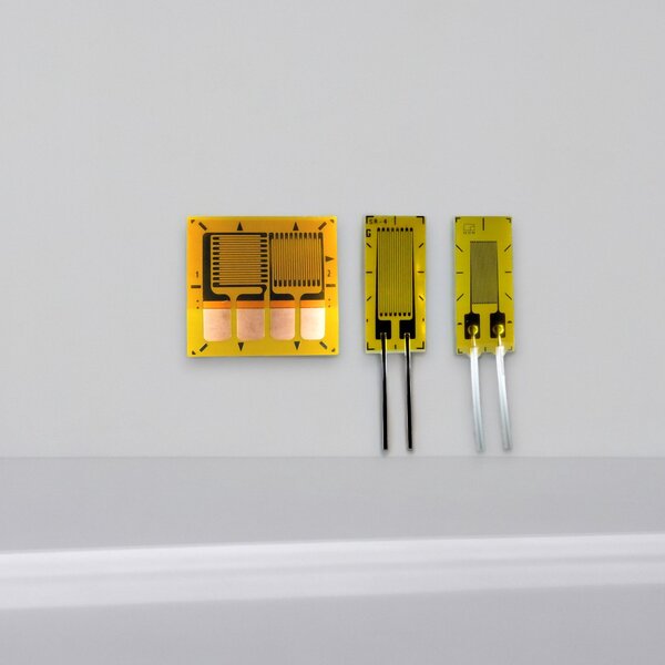
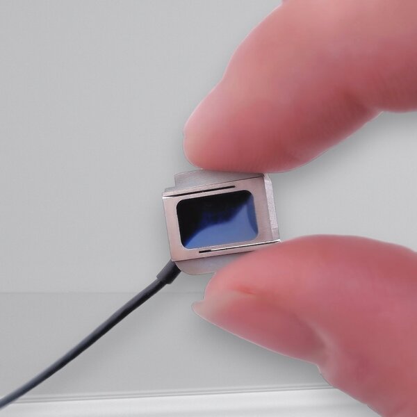
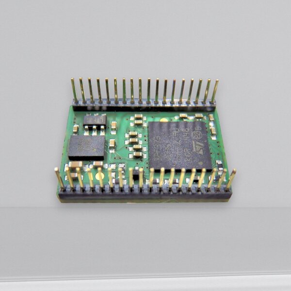
Need help with the installation of strain gauges?

We are glad to assist you with your measuring task and provide all the necessary information about strain gauges.

The training can be customized according to your wishes.

Training agenda (example):

  • Introduction to the strain gauge technique
  • Explanation of typical bridge circuits
  • Explanation of various wiring options
  • Explanation of the steps for the strain gauge bonding
  • Implementation of the strain gauge application for measuring bending, axial force, torsion and / or shear
  • Loading of the component and evaluation of the results with the measuring electronics
  • Calculation of stresses and moments from measured strains

Below you will find the typical steps of strain gauge bonding. They may differ depending on the application.

1. Surface preparation

The DMS application surfaces should have a roughness depth of 0.4 to 1.6 μm before the degreasing and drying is completed.
In this first step, the surface is roughened with an abrasive cloth. Then clean the looped surface in one direction with the lint-free solvent wipes.

2. Mark the strain gauge position

The second step is to position your strain gauge correctly. Just scribble the lines directly on the part with a ruler and a pencil.

3. Strain gauge preparation

Before you glue the strain gauge, find out which adhesives fit best your measuring task.

Strain gauge cleaning with Neutralizer on a cotton swab is also a preparation for gluing.

4. Glueing the strain gauge

Take the strain gauge out of his packing with tweezers and place it with the adhesive side down in the right position on the test object.

Place a short piece of Mylar tape over about 1.5 mm of the strain gauge backing. Raise the composite again at a shallow angle and pull back one end of the composite to pull the strain gauge over the surface.

Coat the entire surface of the strain gauge, including the copper pads, with an adhesive layer.
Also coat the component surface in the area of ​​the strain gauge mounting.

With the help of a polyethylene sheet, press the strain gauge evenly and firmly for about 30 seconds.

5. Check the glueing

Any deviation leads to measurement errors. Therefore, carefully check whether the strain gauge has been glued reliably. You can use a magnifying glass.

6. Soldering the connection wires

In this step, the leads are soldered to the strain gauge.


The selection of solder pads depends on the type of wiring, the solder pad support material, and the size. We are happy to help you.

7. Protective coating of the strain gauge

The sensitive strain gauge circuits require protective covers against most transmitter conditions.

8. Measurement with the electronics

The next step is to connect the measuring amplifier as in our example GSV-8DS. After zeroing, the measurement object is loaded with a given force at different points and then relieved. Thereafter, the evaluation of the measurement results.

9. Calculation of the measurement and troubleshooting

After completing the practical measurements, the stresses and bending moments will be calculated using physical formulas.

+
x

Koensgen, Udo: Wie man eine Miniatur-DMS-Rosette auf eine Leiterplatte installiert (in deutscher Sprache), Youtube.com, 02.01.2018