Mounting of multi-component sensors
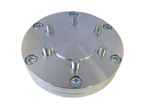
The multi-component sensor consists of a hexapod framework, which is arranged between two plates without additional joints. The sensor is (as a rule) made of one piece of high-strength aluminum (3.1354) or high-strength, ferritic stainless steel (1.4542).
For the function of the sensor, it is crucial that the end faces are not locally deformed.
A local deformation is caused, for example, by a selective application of force Fz in the center of the sensor.
The force is applied flat on the circular ring between the inner centering collar and the outer diameter. The force is applied to the trapezoidal circular segments. The recesses between the segments are not loaded.
In addition to the introduction of force on the circular ring, flatness and rigidity of the connecting flange are important parameters. High-strength aluminum or tool steel 24CrMo4 or C60 tempered or high-strength stainless steel 1.4542 should be selected as material. Plastic flanges from the 3D printer are unsuitable!
An untightened screw can cause measurement errors of the order of 10% or more.
The tolerance for the flatness of the flanges is 0.02mm.
Table 1 gives guidelines for the thickness of the connection flanges and the recommended tightening torque. If the recommended tightening torque exceeds the rated torque of the sensor, then torque should not be passed through the sensor. Instead, it should be held against the flange directly.
The screws should have a minimum strength of 8.8. From 100Nm, screws 10.9 are recommended.
Centering
The multi-component force sensors have a centering collar. (Inside diameter 0 ... + 0.1mm oversize, 1 ... 3mm depth).
In addition, two pin holes are provided for clearance E7 / m6.
To secure the angular position, one of the following variants is recommended (depending on the manufacturing tolerances):
- Use of the centering collar to secure the centering plus 1 centering pin to secure the angular position in a slot
- Use of 2 centering pins: in an E7 hole to secure centering, and in a slot to secure the angular position
- Use of 2 centering pins in two holes E7 to ensure centering and angular position ("double-fit")
- Use of the centering collar and use of 2 centering pins in two holes E7 ("3-fold fit")
If double or triple fits are used, it is recommended to use centering pins DIN 7979 with female thread if they are to be dismounted ...
Materials
If possible, the flange should be made of the same material as the sensor: aluminum sensors with aluminum flange (about 23 μm/m/°C), steel sensors with steel flange (about 12 μm/m/°C). Otherwise, the temperature-related drift of the sensor can be adversely affected by the introduction of temperature-specific voltages.
Mounting position
The sensors can be mounted in any mounting position. As with any force sensor, care must be taken that the connection cable is assigned to the fixed shore (the non-moving flange). Otherwise, forces are applied to the sensor via the connection cable.